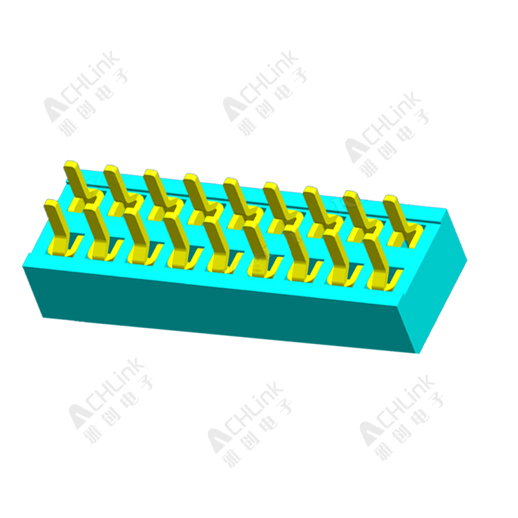
Connector is like the function interface of the program, the design is reasonable, the future product maintenance, upgrade, transplant will be twice the result with half the effort, so that the product maintains lasting vitality; unreasonable design, resulting in future maintenance, upgrade difficulties, pull the whole body, and ultimately make the product lose competitiveness, the importance of the connector goes without saying And metaphorical.
Connector, also known as the engineer's plug-in, is used to connect two circuit boards or electronic devices to achieve power or signal transmission. Through the connector, the circuit can be modularized, the assembly process of electronic products can be simplified, and the products can be easily maintained and upgraded.
There are many kinds of connectors, such as communication interface terminals, wiring terminals, line-to-board connectors, board-to-board connectors and so on. Each category can be subdivided into several classes, such as:
The board to board connector includes pin header, female header, PC104, plate to plate connector, etc.
Pin connector connector

The wire to plate connector includes FPC connector, IDC socket, simple ox horn seat, etc.
For modular circuits, connector selection plays a decisive role, so when choosing connectors, what should we consider suitable for hardware connectors?
1, pin, spacing
Pin number and pin spacing are the basic basis for connector selection. The number of pins you choose depends on the number of signals you need to connect. For some patch connectors, such as the patch pin, the number of pins should not be excessive. Because in the process of SMT welding, due to the high temperature effect, the plastic connector will be heated deformation, the middle bulge, resulting in virtual welding pins. Our P800 Flash programmer used this row of needles and row bushes as inter-board connections in the early years of research and development. As a result, the lead pins of the row needles of the prototype were welded in large areas. After replacing the pin with half the number of 2 pins, there is no virtual welding.
Nowadays, electronic equipment is developing towards miniaturization and precision. The lead spacing of connectors is from 2.54 mm to 1.27 mm and then to 0.5 mm. The smaller the pin spacing, the higher the production process requirements. Lead spacing should be determined according to the company's production technology level, blind pursuit of small spacing, will cause difficulties in production and maintenance.
2, electrical properties
The electrical properties of the connector mainly include: limiting current, contact resistance, insulation resistance and resistance strength. When connecting high-power power supply, pay attention to the limit current of connector; when transmitting high-frequency signals such as LVDS, PCIe and other signals, pay attention to contact resistance. Connectors should have low and constant contact resistance, usually from tens m to hundreds of M ohms.
3. Environmental performance
The connector's environmental performance mainly includes temperature resistance, moisture resistance, salt fog resistance, vibration, impact and so on. Choose according to the specific application environment. If the application environment is relatively humid, the requirements for wet and salt spray resistance of connectors are high, to avoid the metal contact of connectors to be rusted. In the field of industrial control, the anti-vibration and impact performance of the connector is required to avoid the connector falling off during the vibration process.
4. Mechanical properties
Mechanical properties of connectors include plug and force, mechanical, etc. Mechanical stall is very important to connectors. Once inserted, it is likely to cause irreversible damage to the circuit.
The insertion force is divided into insertion force and separation force. The maximum insertion force and the minimum separation force are stipulated in the relevant standards. From the point of view of use, the insertion force should be small and the separation force should be large. Too little separation force will reduce the reliability of contact. However, for connectors which often need to be plugged and pulled, too much separation force will increase the difficulty of pulling out and reduce the mechanical life.
P800 Flash programmer used the horn connector as the connector between the programmer and adapter board in the early development process. This connector has tight contact and low cost. The drawback is that mechanical isolation is not obvious and the separation force is too large. In the process of replacing the adapter board of the programmer, the couple of connectors can be separated by means of tools such as tweezers, which affects the user experience.
In order to solve the problem of excessive separating force of connector, we designed a complicated auxiliary puller, which increased the cost, but the pull-out effect was not obvious.
After that, we designed a sheet metal cover plate, fixed the adapter plate to the cover plate, and realized the purpose of separating the connector by pulling the cover plate. The actual test result is not ideal, even the phenomenon of connector plastic cracking and pin skew appears.
In order to reduce the splitting force of the board-to-board connector and facilitate the user to plug in and pull out the adapter board, we made a lot of attempts, and finally found a light on the road of exploration. Finally, we chose the connector shown in the following figure, and modified the PCB and the product shell structure.
The actual test shows that the connector has a unique orientation, obvious anti-staleness effect, small insertion force, moderate separation force, good insertion and pull-out feel, greatly improving the convenience of the use of plug-in and pull-out parts.

